"Chipping" an extension ringMost Nikon DSLR bodies in the consumer and semi-professional classes cannot meter, unless the lens is of the CPU type (i.e., it has built-in electronics). Currently, this is true of the D100, D70, D70s, D50 and D80 (as well as a few film SLRs). If you want to use an older lens without CPU, a special-purpose lens of a different brand, a lens mounted on bellows, or a microscope or telescope in place of a camera lens, you are out of luck. Only manual exposure (i.e., no light metering) is available with this equipment. Professional camera bodies do allow you to meter and expose automatically also with non-CPU lenses, albeit with a few limitations. The solution, apparently discovered independently by a few photographers, is to scavenge the electronics from a discarded CPU lens and transplant it into the desired equipment. This technique has been used, for instance, to convert old Nikkor super-telephoto lenses with manual focusing to allow them to meter with modern camera bodies (autofocusing with them is obviously impossible, if they have only manual focusing to start with). Lenses or accessories modified in this way are often referred to as "chipped", meaning that they have had a chip added (not that you have broken off a small piece of them). As far as I know, this procedure is not carried out by commercial laboratories (including Nikon's). One or two individuals do or did offer this service on a commercial, home-run business basis, with much variable degrees of satisfaction reported by their customers. I have no first-hand experience with these individuals or their customers, and therefore I cannot have any personal opinion or recommendation. I do not offer this service, and the advice on this page is the only thing I provide. The procedure differs from lens to lens, and requires the bayonet mount of the lens (and often, other parts of the mount as well) to be modified. Usually, this involves a rather complex series of operations, which include careful planning, disassembly, filing and cutting both metal and plastic parts, drilling small holes with close tolerances on slippery and curved surfaces, and reassembly. The electronics are also sensitive to static electricity, and it is entirely possible to destroy them by inappropriate handling. As a whole, you should not attempt this procedure unless you know what you are doing and have the necessary tools. Of course, all such modifications void any warranty on the lens, and may easily damage your camera body if done improperly. Do anything at your own risk. On this page, I provide a general background of the procedure of chipping an extension ring. A chipped ring can be mounted at the back of bellows, macro lenses, microscope and telescope adapters etc., and therefore is a versatile accessory for macro photography. It can be used also with long telephoto lenses, but of course you will not be able to focus them at infinity with the ring attached. A few other web sites provide comparable discussions about chipping extension rings and lenses. By all means, check out as many as you can find, before attempting the operation. A necessary step in this operation, of course, is obtaining a discarded, or low-value, lens from which to extract the circuitry and contacts. Although Nikon may provide these as spare parts, they are not going to be cheap. While living in Japan, I was regularly visiting local camera stores to inspect their junk bins. They frequently had broken CPU lenses (and sometimes, still usable ones) on sale for a very low price. Of course, there is no guarantee that the CPU is still working. If the lens is a cheap plastic zoom that has been dropped and has an obvious mechanical fault, there are good chances that the electronics are still good. On the other hand, lenses of good quality, with metal barrels and sturdy construction, are less likely to have mechanical faults. In fact, their mechanical construction is less likely to break than their electronics. Especially if they show no obvious mechanical fault, there is a chance that the reason why they were discarded is an electronic fault. If you do not have access to discarded lenses, your best bet is a second-hand camera store, or an auction site on the internet. However, these sources usually sell functioning lenses, and you should be prepared to spend more than for junk. Electronic connections between camera and lens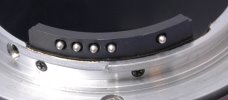
CPU lenses possess a variable number of electrical contacts on the inside of the lens mount (above). These contacts transmit information between the lens and the camera body. Depending on the number of contacts and type of lens, information sent by the lens to the camera includes the widest aperture of the lens, its focal length and the focus distance (in D lenses). The camera body provides power to the lens electronics (and VR system when present) and autofocus signals (in AF-I, AF-S and HSM lenses). If a consumer or semi-pro Nikon DSLR does not receive signals from a lens CPU, it cannot meter. This is why it is necessary to transplant the CPU circuits and contacts into an accessory or lens, to allow it to meter with these cameras. If you scavenge the circuits from a G-type lens (i.e., the ones without the aperture ring), the above operation is all you need. However, you may have the circuits from an older lens (one with an aperture ring) available. In this case, you need to add an external tab near the lens mount, in order to close a switch on the camera body. Without this, the modified lens or ring will not work. The reasons for this are explained in the next section. I have had a low rate of success with circuits scavenged from non-Nikkor lenses. It is possible that I have been simply unlucky, and that the broken Tamron and Sigma lenses I got had a busted CPU. Perhaps, a good CPU from one of these lenses would work just as well as an original Nikon one. Nonetheless, after my initial experience I bought only broken Nikkor lenses to extract the CPUs. Mechanical connections between camera and lens
There are also a number of mechanical connections between lens and body, some of them obsolete and not used in modern bodies. For example, in older lenses the top of the aperture ring used to carry "bat-ears" (1, above) to inform the camera of the value of the aperture set with the ring (bat's ears are also known as the meter coupling prong). Inside the lens mount, a lever on the right side of the lens (2, above) transmits the command from the camera to stop down the diaphragm during exposure. If this lever is missing (e.g., in bellows and manual extension rings), the diaphragm stays closed to the settings chosen with the aperture ring. Mechanical autofocus uses a slotted pin mounted on the flange of the bayonet, on the lower right side of the lens. This connection is missing in lenses with electronic autofocus. The retention pin that prevents the accidental dismounting of a lens from the body matches a hole or slot on the bayonet flange, on the left side of the lens (3, above). 
In modern lenses (except the G series), the back rim of the aperture ring carries two cams. One of them (also known as meter coupling ridge) is longer (arrow, above), and was meant to inform older cameras about the available range of apertures, as well as the value of the aperture set by turning the ring. 
The second cam (also called EE servo coupling post) is much shorter (arrow, above), located on the right side of the lens mount, and is still used by DSLR bodies. Without this cam, a consumer Nikon DSLR (D100, D70, D70s, D50, D80) refuses to acknowledge that a lens is attached. This is the same thing that happens if you forget to set the aperture ring to its minimum (i.e., highest f/value) setting. This is done purposely to set the aperture automatically through the camera's exposure system, or manually through a dial on the camera body. With these cameras, the aperture ring on the lens is purely ornamental, and has lost any function. The aperture ring comes back into function (as a manual preset) only if the lens is mounted onto an accessory (bellows, extension ring, teleconverter) that separates it from the camera body. Note, however, that pro and semi-pro Nikon DSLRs (D1 series, D2 series and D200) do have a lug that engages the meter coupling ridge, but don't have one for the EE servo coupling post! On the other hand, these cameras are not really relevant to the present discussion, because they can meter with non-CPU AI lenses and accessories, so they don't need chipped accessories like the ones described here. There is a good reason to remember this difference, which is mentioned later on this page. 
Teleconverters and extension rings often have both cams. The large one is built as a transmission that relays the position of the aperture ring from the lens to the body (arrow, above). 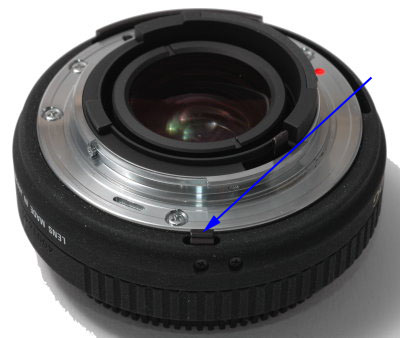
The small cam can be built in two different ways. In some of these accessories, it is a transmission like the large cam. In others, it is a fixed tab, and therefore it closes the switch on the camera body even if a corresponding cam is missing on the lens, or if the aperture ring is not turned to the smallest aperture (arrow, above). To keep things simple, you should try to build this cam in the same way as the second type, so that it closes the switch on the camera body without pressing too hard on it. There is a sideways tolerance of at least a couple of mm between the point where the switch closes and the point where pressing it further is likely to cause damage, so the position of this cam is not very critical. Older lenses have additional mechanical tabs and couplings. They are not relevant to chipping, and therefore I do not discuss them here. This site contains a detailed escription of almost anything that has to do with the Nikon F bayonet and its couplings Notes on the chipping procedureSo far, I have disassembled three Nikon extension rings, and in all three cases one of the screws attaching the rear bayonet to the ring barrel was immovable (apparently glued in place). In all cases, I was unable to unscrew it without damaging the screw or the bayonet flange. This was not a problem for me, because I intended to change the bayonet mount in any case, but if you have the same problem you may try heating up the screw head with a pin-point butane torch. Most types of glue will melt or decompose when exposed to heat. The CPU circuit board has a different shape and size, depending on the lens make and model. Often, it is necessary to disassemble the lens almost completely, in order to remove the circuit board. The back of the circuit board usually is attached to an internal barrel surface with bi-adhesive tape. Removing it without damage requires care. The circuit board of modern lenses is built on a thin, flexible substrate. This is easier to work with than older, rigid circuit boards. You should always avoid bending a circuit board (including a flexible one) where components are soldered to it. 

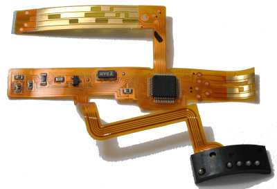
Three chips are shown above. The first one has components soldered to a rigid circuit board (green). The two others are more modern, and built entirely on flexible circuit boards. The last one has two rows of wiping contacts (see below) and comes from a D-type zoom. The first two ones have only one row of wiping contacts each, and both come from non-D zooms. I cut the zoom wiping contacts off in all three circuits, but the last one still has the distance contacts (see below) and part of the zoom contacts. In the second circuit, I soldered a bridge (red wire) to simulate the settings associated with a specific focal length setting of the zoom ring. The contacts that connect the circuit board to the camera electronics are housed in a black plastic block. You should leave the contact block attached to the circuit board. The circuit board of D-series lenses has also a strip of wiping contacts that is shorted by a mobile "comb" attached to the focus ring. A unique combination of contact pads is exposed at each position along the contact strip. This is used to detect the focus distance. Usually, there are just 6-8 possible combinations of contact pads, so the focus distance signal is approximated to one of these possible values. In zoom lenses, another contact strip detects the focal length and is wiped by a comb of shorting contacts attached to the zoom ring. Prime lenses have only one contact strip (in D-lenses) or none (in pre-D lenses). Thus, you may have circuit boards with two, one or no wiping contact strips. Ideally, you should try to obtain a circuit board of the last type (e.g., from a non-D AF 50 mm f/1.8 or f/1.4), because it is likely to be smaller and easier to fit into the available space. These circuit boards, as a rule, are also easier to remove without damage from their original lenses (sometimes, they are attached only to the bayonet mount, and no further lens disassembly is needed). Note that there is no wiping contact strip for the aperture ring - the camera body simply has no electronic way to read the aperture chosen with this ring. If you want, you can solder thin wire bridges at an appropriate position across either wiping contact strips, to select a particular focal length and focusing distance. This has the result of simulating the presence of the comb of shorting contacts at the same position. In practice, I have found that this is not necessary. In fact, I cut away both contact strips entirely, with no side effects (as long as there are no components soldered on them). This reduces the size of the printed circuit board, and makes it easier to fold it up to fit the available space inside its new home. It may be necessary to cover the component side of the circuit board with tape to prevent short-circuits against a metal housing. The opposite side usually is insulated, and needs no tape. 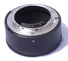
The above figure shows a Nikon PK-13 ring I chipped. The conversion process did not go as smoothly as I planned - more about this later. The original PK-13 is a manual ring, with no electronics and no mechanical autofocus transmission. It has a length of 27.5 mm, and therefore provides plenty of internal space to house a CPU circuit board. The electric contacts for the internal lens electronics are housed in a curved black plastic block, usually attached to the lens mount by two small screws. The two screws pass through holes in the bayonet. It is difficult to make such holes in a bayonet mount, because their position must be precise (within about 0.2 mm), but their position is not close to any other "landmarks", so the plastic block must be positioned within the bayonet for marking the hole position (there are additional problem in this, because in this way you mark the holes on the inside of the bayonet, but they are best drilled from the outside). Of course, the rear bayonet of this ring does not have already any usable holes in the right positions, because it does not carry a contact block. Also, contact blocks from different lenses have the holes in different positions, and may require a different thickness of the bayonet in order to sit in the proper position (which involves filing and other adjustments). All these problems may be solved if you are technically inclined, but there may be an easier way. Since you are scavenging the electronics and contact block from a lens, you can just as well recover the bayonet mount of this lens as well. With a little luck, it will fit with little modification (e.g., wider screw-holes) in the accessory you want to chip. If you are very lucky, no modification is necessary, and the only problem left is finding a suitable space for housing the electronics. There may be space available between two barrels or baffles, or directly inside the ring/lens/bellows (in this case, they are best covered with black matte tape to prevent reflections). The bayonet mount of the lens I had available had a built-in baffle with a small central hole to let the light pass. To avoid possible problems with vignetting (a real possibility in high-magnification macro), I filed away all extra metal and ended up with a hole of the maximum diameter allowed by the bayonet mount (about 40 mm). Of course, you must detach the contact block before carrying out similar operations. In my case, the ring had two mechanical transmissions. To start with, there was an internal transmission for closing the diaphragm during exposure, attached to the rear bayonet mount. Since I changed the latter, this transmission was already eliminated. Otherwise, you are probably better off by taking it away. There were also a transmissions for the larger cam on the aperture ring (attached to a rotating sleeve located between the outer and inner fixed barrels), and none for the smaller cam. Since the larger cam is useless with consumer-level DSLRs but the smaller one is needed, I disassembled the transmission, cut away its front cam, rotated its back cam into the position needed for the smaller cam, and epoxied it in place. This is the reason why, in the above figure, the larger cam is seen in an unusual position - it is just filling in for the small one. You should remember that this "hack" makes the ring or lens incompatible with pro-level DSLRs (D1 and D2 series, and D200). Depending on the type of ring you are using and the length of its meter coupling ridge, it may even damage a pro camera body if force-mounted on it. Therefore, repeat with me: accessories and lenses with a meter coupling ridge relocated to function as an EE coupling ridge are to be used only on consumer bodies! If you use both types of cameras, you should file off the excess length of the relocated meter coupling ridge, which removes the possibility of damaging pro bodies. The chipped accessory still will not work properly on a pro body, but at least it will not damage the camera. While I was looking for a place to house the electronics, I realized that I could cut out part of the moving internal sleeve to create the needed space, so I did this before gluing the sleeve in place with epoxy. This shows that it is a good idea to try and play around with all parts before performing irreversible operations. Some more filing of the inner barrel provided a space for passage of the electrical connections between the rear contact block and the circuit board. Once I finished the job and tested the extension tube, I discovered that the CPU was dead. I do not know whether it was already dead when I got the lens, or died later during my handling. Fortunately, I had a broken Nikkor with plastic bayonet available. I could not used the plastic bayonet (which was one of the broken parts), but the contact block had screw holes in the right places to fit into the bayonet I already mounted onto the extension ring. The thickness of the bayonet metal was excessive, but filing took care of this. At the end, I had a working chipped extension ring. I have since chipped a second extension ring. Originally, this was a Kenko teleconverter, but removing its optical elements effectively turned it into an extension ring. It did have electrical contacts on its front and rear bayonets, but it still needed chipping. It also had a fixed small cam in the right place near the lens mount, so I did not need to make one. A teleconverter usually contains only straight electrical connections between its front and rear contacts or, in the best case, some electronics to change slightly the signals coming from the lens. This is not a substitute for a lens CPU. The rear bayonet of the teleconverter already had drilled holes for a contact block, so I thought I could use them. I also intended to investigate the possibility of attaching a CPU circuit board to the teleconverter's rear contact block. I quickly discarded this idea when several miniature springs and other metal parts flew merrily away once I opened the contact block to expose the contacts, never to be seen again. In any case, they were far too small and numerous for me to consider reassembling them, and the spacing between the contacts did not match the spacing between tracks on the circuit board I planned to use. Unfortunately, at that time I could not find a lens with a contact block compatible with the Kenko bayonet, and the rear bayonets of the lenses I had available were also incompatible as an exchange for the teleconverter's one. Thus, I resorted to using a bayonet that did not have holes for the contact block, and to epoxying in place the contact block on the inside of the bayonet. I intended to test how long this would last. In fact, it is still working fine after almost one year of infrequent use, and I don't see any sign of the block coming loose. Dropping the ring to the floor with the contact block lowermost probably would detach it, but then probably it would also break a screwed-on contact block. I am always storing my extension rings with front and back caps to prevent contamination by dust, so the contact block is not in risk of being squeezed when inside a bag or pocket. Using a chipped extension ringMy first tests of the chipped extension ring gave mixed results. Some sessions showed a correct exposure, others an obvious under- or overexposure by several stops. It turned out that I had missed one crucial piece of instructions when reading web pages about chipped extension rings. Since the CPU has no way to know or to set the actual aperture, and exposure time is measured with the lens diaphragm closed to its exposure value, the aperture dial on the camera body must be set to fully open whenever the chipped ring is mounted onto the camera. The camera remembers the last aperture set on the last lens you used, which likely will not be fully open. Thus, unless you tell the camera that the diaphragm is to be set to fully open to the aperture reported by the CPU as the maximum lens aperture, the camera believes that the diaphragm will close further during exposure (which does not happen because the diaphragm of the lens is already preset to its exposure value), and the exposure will be off. At least in theory, cutting off the contact strip of the focus ring from the circuit board of D-lenses may cause the CPU from reporting the wrong distance information to the camera. While this seems to have no effect with continuous sources of illumination, it could conceivably cause a wrong exposure with an iTTL flash like the SB-800. However, I have not had a problem because of this. It has been remarked that the distance information provided by D-lenses affects only a small minority of flash situations. So, you are not likely to have this type of problem. Although you may also chip bellows, I do recommend that you use a chipped extension ring mounted at the back of the bellows instead. Aside from the fact that this adds flexibility, and that you can use the same chipped ring on a variety of equipment, the rear bayonet mount of bellows is often of a special type, which makes the operation more complex. It is also more difficult to house the circuit board inside bellows, where it may become bent or scraped when you change the length of the bellows. |