AmScope LED 50W fiberoptic illuminatorAfter a few years spent moving house around Sweden (six times since the start of my retirement) and associated remodeling work and endless unpacking and repacking of my stuff, I am starting to organize my things in our new apartment on the shore of lake Mälaren in the center of Västerås, a mid-sized city in central Sweden. Probably my largest (in more than one sense) unfinished project is setting up, completing and modifying an Olympus BX50 microscope, and several other micro- and macroscopes. Part of this project includes upgrading the original halogen and mercury-arc light sources to LED. While DIY solutions are possible to convert ordinary microscope illuminators to LED, converting halogen fiberoptic illuminators to LED sources is not feasible, or the results are too uncertain. The internal optics of the two types of illuminators are different, for one thing. Thus, I decided to choose a commercial ready-to-use solution for a LED fiberoptic illuminator. AmScope is a long-time US-based microscope maker/marketer offering 20W, 30W and 50W LED fiberoptic illuminators through both AmScope and third-party resellers in many countries, including US and EU. Their prices are significantly higher in the EU, but still quite competitive compared to other well-known brands like Volpi, Schott, Olympus and Zeiss. Products of the latter brands are targeted mainly to research and biomedicine, while AmScope targets mostly home and educational users. However, except for extremely parsimonious sales literature, I was unable to glean any significant technical information from the AmScope sites. My attempts to prompt opinions from current owners of these illuminators on photomacrography.net/amateurmicroscopy.net and MicrobeHunter.com failed to receive any replies. Possibly these AmScope fiberoptic illuminators are a recent addition to their inventory. These illuminators are made in Chinese factories, like virtually all of current AmScope's inventory. Note that this page discusses real LED fiberoptic illuminators. There are plenty of illuminators for stereomicroscopes, especially on eBay, Alibaba and AliExpress, that look superficially similar to fiberoptic illuminators but consist of LEDs mounted on tiny heatsinks at the end of gooseneck arms. The latter only contain an electrical cable to power the LED, instead of a bundle of optical fibers. Often, unscrupulous sellers unashamedly call them "fiberoptic illuminators". Other sellers do not explicitly call them "fiberoptic", but avoid discussing the difference from real fiberoptic illuminators. I chose the 50 W AmScope model because I may want to use it also as illuminator for compound microscopes, where techniques like darkfield and DIC "eat up" a large portion of the illumination. 50 W from an LED is very roughly equivalent to 200-300 W from an incandescent bulb, or 150-200 W from a halogen bulb. 50 W LEDs are painfully bright at the fiberoptic port of the illuminator without a connected gooseneck, and you should never look straight into the open illuminator port, on into the end of the optic fiber. You should also form a habit of turning the illumination intensity knob all the way counter-clockwise before turning on the illuminator. For these reasons, 50 W LED fiberoptic illuminators are perhaps not the best choice for a school classroom, where students may be unaware of the danger to their sight and do stupid things. A 10 W or 20 W illuminator may be safer in this respect, although 10 W is already painfully bright. However, in the hands of a careful and moderately experienced user, the more light is always the better for most types of microscopy. A LED fiberoptic illuminator is still far less dangerous than many other types of optoelectronics, like infrared laser diodes that can burn a hole in your retina without giving you any discomfort. PackagingThe illuminator was shipped to me by AmScope Netherlands in a large but not so strong corrugated carton box, the extra space taken up by crumpled paper. A smaller box inside contained the various parts in a form-fitted rigid foam insert. This insert also has space for a folded light guide, which was empty in spite of the fact that the item I ordered is an illuminator with single light guide. The light guide was instead squeezed, without any padding or wrapping, between the bottom of the large box and the smaller box. The smaller box had originally been sealed with tape, but I received it with the seal cut open. The large box does not appear to have been opened and re-closed, and none of the parts shows any sign of use, so it appears that someone opened the smaller box before shipment but did not re-tape it close. Nowhere in the shipment is any trace of user manual or other documentation, except for a packing list. If I want to learn more, I will have to disassemble the illuminator. External characteristicsFirst of all, I am aware that the illuminator I received differs externally in several respects from the product pictures on the AmScope web site. There are obvious differences in shape and placement of ventilation holes, size and color of the mount for the light guide, shape of the adjustment knob, mounting direction of the rear fan and shape of its blades, and distribution of logos and labels on the front panel. The model number on the front panel also differs (LED-50W on mine, FOI-5WW on the AmScope site). However, the web-page of the product on the AmScope site is named led-50w, i.e. like the product name on my item. 
My 50 W model was delivered with a Chinese third-party "brick" switching supply providing 24 V DC 3 A, in theory capable of supplying a maximum of 72 W (Figure 4). The power supply automatically adjusts to line voltages between 100 and 240 V AC. It accepts a power cord with a C13 female connector. In spite of my order being shipped from the EU, it came with a UK power cord and a UK to EU adapter. I replaced this cable with a proper cable with the EU standard "Schuko" CEE 7/4 plug used almost everywhere in the EU, because the adapter looks unsafe to use (one's fingers get uncomfortably close to the metal terminals of the UK plug if the latter is not fully inserted). A separate power supply does take more space on or under a table than a power supply built into the illuminator. However, brick-type solid state switching power supplies these days are cheap and very common, and an external one eliminates the problem of finding a matching internal power supply if the original one goes bad. The external or internal power supply is probably the part most likely to go bad in the lifetime of an illuminator. The power supply has no power switch and is always on (as indicated by a blue LED) when the power cord is connected. I can feel no heat on the surface of the power supply when the illuminator is switched off, so the idle power consumption at zero load is probably negligible. 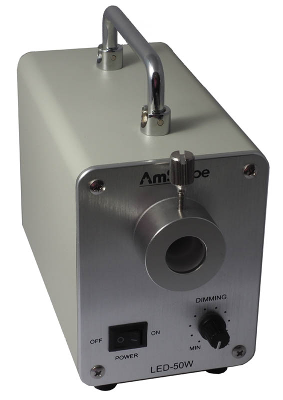
The case of the illuminator feels strong, and is entirely made of metal. The rear panel only has a power jack and ventilation slits (not a grid like in the AmScope picture) for an internal 60 mm cooling fan. Two ventilation openings, protected by a metal net, are present at the bottom of the case, together with four rubber feet. There are no ventilation slits on the sides of the case, unlike the AmScope pictures. A solid metal folding handle at the top of the case is used for lifting the unit. A largish heat sink is visible through the bottom netting. A cluster of four closely spaced LED dies is visible through the port for the light guide. There are no externally accessible fuses. There is a power switch on the front panel of the illuminator casing, together with a potentiometer and the port for the light guide. The 3/4 turn potentiometer adjusts the light intensity. With the knob turned all the way to minimum, the light is already relatively strong, almost enough for use with a stereomicroscope at low magnification. It becomes visually only slightly brighter while turning the knob half a turn, then in the last third of the travel the light gets quickly brighter and brighter. A short distance from the end stop of the potentiometer, the brightness suddenly jumps to at least double, and there is no way to adjust it at an intermediate brightness. I guess this is one of the reasons why this illuminator is cheaper than its counterparts of other brands. It might be feasible to replace the potentiometer with a better one, perhaps a multi-turn one. The front and rear panels are attached to the casing with four Phillips crosshead screws each. Each rubber foot is fastened with a small screw, which also anchors the PCB assembly within the case (before removing these screws, see the disassembly instructions below). The clamping mechanism of the light guide presses a wide spring-loaded aluminum half-ring against the neck of the light guide, which is nicer than a thumbscrew directly pressing against the neck and leaving a permanent mark. The length of the thumbscrew is however excessive. There is no use for such a long screw, because fully tightening the clamp to the point where the aluminum half-ring no longer can move still leaves 7 mm of screw threads visible. The large head of the thumbscrew covers the middle of the AmScope logo on the front panel. In a piece of DIY equipment, these might be details without practical importance, but in a relatively expensive commercial product, I regard them as embarrassing design oversights, or perhaps the result of laziness and corner-cutting (e.g. failing to order thumbscrews of the right length and head size from a supplier, and then to shorten them in-house to the right length). It would also have been easy to put the logo somewhere else, or to rotate the light guide collet to one side and use a more modestly sized thumbscrew, like done on e.g. some Hoya-Schott illuminators in my possession. InternalsDisassembly
There are no warranty seals on this unit, nor any compliance declaration. The eight screws on the panels must be removed first, freeing the front and rear panels. The cables connecting to the various panel controls are long enough to allow the panels to be laid down on the table near the body of the illuminator. At this point, turn the body on one of its sides. While holding the internal electronics with one hand to prevent them from falling, remove the screws of the four feet. Once this is done, the whole contents of the illuminator can be slid forward and out of the case. The case itself is a single section of extruded aluminum profile. There is no need to remove the top handle. The metal netting protecting the openings in the bottom of the case also comes free with the interiors. It is very thin and quite delicate, so handle it with care. DescriptionThe PCB is attached by three screws to a remarkably heavy brick of metal, painted black with a thick layer of epoxy-like paint (Figure 3). I suspect that the metal is iron, but might alternatively be a lead alloy. The only purpose of this brick is to provide enough weight to prevent the illuminator from tipping over from the weight of an attached light guide. In turn, the metal brick is attached to an aluminum plate by two screws. This plate also carries four threaded screw holes, where the feet screws fix the plate at the bottom of the case. The port for the light guide carries internally a plastic collar, in correspondence of the external mount for the light guide. The latter is also mostly made of plastic, but clad in an aluminum sleeve. The hole for the light guide is 20 mm wide, but restricts to a diameter of 16 mm at a depth of 14.7 mm, then continues inward for another 13 mm before reaching a slight ledge that stops movement of the light guide. The base of the LED package is a round aluminum disk, with a diameter of 45 mm and a thickness of roughly 2.5 mm, attached to a heat sink cooled by a second 60 mm fan. This fan blows out from the heat sink and toward the case fan, not toward the cooling fins as typical of heat sink fans. It may be that this is a design compromise to blow air toward the small black heat sink on the PCB and cool it in the process. The fan attached to the rear panel blows air outward, which is the usual way. The potentiometer carries no visible value or type markings, and a precise measurement of its resistance would require it to be unsoldered, which I am not doing right now. The wires are heat-shrink coated on the potentiometer side, and hot-glued on the side soldered to the PC board. 
At the back of the heatsink are an XL4016E1 DC-DC voltage converter (right) and an SB1660CT double Schottky diode (left). The wires to the fans (rightmost) are soldered by hand to the legs of a voltage regulator IC. I am not going to reverse-engineer the internal circuitry, but nonetheless I can comment on what is visible. The PCB is sparsely populated with a small number of components. Several soldering pads for capacitors, resistors and semiconductors are unused (Figure 4). A few of the unused soldering pads are shorted with blobs of solder. Some of the unused pads are duplicates of used ones, but not all. As a whole, the actual circuit implemented on the PCB seems to be an extreme simplification of the original, already simple design. Hopefully, the simplified circuit does not compromise on the basic function of preventing the LED from overheating in a thermal runaway. Power to the LEDs uses only two wires. 
Two electrolytic capacitors and a high-frequency inductor coil with a doughnut ferrite core are tucked away below the PCB (Figure 5). All wires are soldered directly to the PCB, to soldered PCB terminals, or to the legs of components, and there are no connectors to unplug. There are no fuses anywhere, so the electronics simply rely on the power supply to cut off in case of overload. Both fans use only two wires and run at a constant speed regardless of internal temperature. Heatshrink-coated resistors are soldered along the fan wires to the PCB, apparently not as part of the original design, to reduce the fan speed and noise. The fan wires are directly soldered to the legs of a voltage regulator IC, another strange decision that makes the product look like an improvised DIY. The heat sink fan is noticeably noisier than the fan on the rear panel and presumably runs faster. The circuit has no way to detect whether the fans are operating. If one of the fans should fail, there is no doubt that the internal temperature of key components will rise significantly. The DC-DC converter IC has a built-in thermal shutdown, but there seems to be no circuitry to sense and limit the temperature of the power LEDs. 
The external case and internal metal plate carrying the PC board are not grounded. Lightly brushing the edges of the aluminum base with a fingernail releases abundant chips that almost look like metal, but might be mostly paint or dried-up cutting fluid mixed with aluminum dust (Figure 6). Sharp edges on the heat sinks and other metal parts, thin and haphazardly mounted metal netting to protect the air intake at the bottom of the case and a generally rough finish of the metal parts in the interior stand in sharp contrast with the neat and smooth external appearance. Temperature testI measured the temperature with a contact thermocouple probe clamped to the LED heat sink as close as possible to the LED carrier. This is not a measurement of the LED chip temperature. Running the illuminator with its interiors spread on a bench as shown in Figure 3 is not a completely realistic test, since heat buildup within the case may produce somewhat higher temperatures in normal use. Nonetheless, starting from an ambient temperature of 23.5 °C, after 10 minutes of running with the LED at maximum power, the heat sink temperature in proximity of the LED package rises to 43.4 °C. After another 10 minutes, the temperature is 44.8 °C, which remains close to stable afterwards. This means that the heat sink in proximity of the LED gets roughly 22 °C warmer than air temperature, which with a theoretical load of 50 W implies that the fan-cooled heat sink dissipates around 0.5 °C/W. This is a fairly average performance for a largish fan-cooled heat sink. During this test, the small heat sink on the PCB, not cooled by the fan in the present configuration of the components, is hotter (around 55 °C) than the LED heatsink. This suggests that my idea of the heat sink fan serving a dual purpose is likely right. At the same time, a bigger heat sink on the two power ICs, better oriented to take advantage of the direction of air flow in the case, would make the device run cooler and potentially less likely to fail. A further observation related to temperature tests is that, with the illuminator reassembled and the single-gooseneck light guide mounted on the illuminator port, the base of the light guide near the port becomes quite hot (around 60°C) after 20 minutes of continuous use at full power, but the opposite end of the light guide remains cool to the touch. We can therefore acknowledge that this illuminator fulfills its promise of being a "cool light source", even at full power. Naturally, no light source can be completely cool, because any light absorbed by the subject, at any wavelength, is unavoidably converted into thermal energy (with the exception of radiation re-emitted as fluorescence). Why the base of the light guide becomes so hot is also worth of some thought. It does not seem to contain a heat-absorbing filter, but the optical fibers themselves might absorb IR. Much of the heat may also come from off-axis light absorbed by the collet and by the entrance to the fiber bundle. The net result is that the temperature at the external base of the light guide becomes higher than the temperature I measured on the LED heat sink. An external heat sink at the base of the light guide, or at a minimum a sticker with a warning about high temperature, would not be out of place, given the proximity of the light guide mount to the controls on the front panel. Illumination stability testThis test was run in a dark room, with the illuminator reassembled in its case, the supplied single-gooseneck light guide, and a Sekonic Flashmate L-308S exposure meter. In previous testing, this exposure meter has provided a repeatable precision of ±0.05 f/stops. Photographic exposure is normally measured in stops, which is a non-linear measurement. The scale of f/stops typically reads 1, 1.4, 2, 2.8, 4, 5.6, 8, 11, 16 etc. At a constant exposure time and ISO sensitivity, an increase from one value on the above scale to the next, e.g. from 4 to 5.6, corresponds to a doubling in illumination intensity of the subject. Initially I placed the meter's sensor 5 cm from the end of the light guide, and obtained almost constant readings around f/8 over the span of 30 minutes. I thought it was possible that in this test the high illumination level caused a non-linear response of the sensor, and therefore unreliable results. The meter, however, did not display any out-of-range indication. To be on the safe side, I repeated the test with a distance of 15 cm, which gave readings around f/4. The difference over the span of 30 minutes, however, remained much the same as in the initial test. The meter's sensor was covered by its hemispheric diffuser for incident illumination and placed at the arbitrary distance of 15 cm in front of the end of the light guide. The light meter was set to continuous illumination mode, a sensitivity of 100 ISO and an exposure time of 1 ms. This is not a test of the absolute intensity of illumination, and its purpose is only to measure whether the illumination intensity remains the same immediately after switching on the illuminator, and at intervals of 10 minutes while continuously operating the illuminator at maximum power. The initial reading gave an exposure value of f/4.02, and subsequent readings at 10 minutes interval f/4.01, 4.00 and 4.00. The total drop was 0.02 stops over 30 minutes. This drop is within the error margins of the measurement instrument, and in practice completely undetectable in all visual and photomicrographic applications I can think of. I repeated the test with an LX1330B luxmeter, which has its peak sensitivity at 550 nm according to the instrument documentation. The results are 660 lux initially, and at subsequent intervals of 10 minutes 609, 602 and 599 lux. This corresponds to a drop of 9.2% over 30 minutes, at which point the readings became largely stable. Such a drop is also essentially undetectable in practical imaging. It would also be interesting to monitor the current and voltage at the LED during the same test, but for the moment I am not going to unsolder the LED wires. Spectral emission testFor this test I used a Lasertack LR2 spectrometer with sub-nm resolution and a 200-1200 nm range. Since the illuminator has no significant emission below 400 and above 700 nm, I omitted these ranges from the graph. 
The sharp peak in the blue (about 450 nm) is typical of "white" power LEDs, which use a blue-emitting LED core and a downconverting phosphor mixture to emit green and red light. The performance of this illuminator is typical for current mass-produced white power LEDs. Color fidelity is rather poor in the color ranges roughly corresponding to purple, cyan and deep-red tones. There are better LEDs that use different principles to emit a more uniform spectrum (for example purple or near-UV LEDs that stimulate a phosphor mix that emits blue, green and red light), but they are expensive and generally not very powerful, so I would rate the spectral emission of this illuminator as acceptable at the given price range. Figure 7 shows the spectral emission at maximum power (blue) and minimum power (red). Both diagram lines were equalized to their respective maxima (i.e. the peak of the blue LED emission). It can be seen that the spectral emission changes with power. The blue emission peak becomes narrower and slightly shifted to shorter wavelengths at low power, and the phosphor emission also becomes proportionally lower than the LED emission, giving as a whole a "colder" color balance at low power. This is just the opposite of how a halogen or incandescent light source behaves. In applications where color repeatability is necessary, this illuminator will not perform very well, unless imaging is consistently done at the same illumination intensity. ValueAlthough this AmScope illuminator is cheaper than the corresponding products of well-established competitors, it is still overpriced for what it contains. Given the lack of information and discussions on the web at the time of writing, these illuminators seem to have been recently introduced by AmScope. Only time will tell how durable they are. One can also hope that newly produced batches will use better and more reliable electronics, which cannot be much more expensive to produce than the current minimalistic circuitry, and would help AmScope to potentially reduce the number of failed units during the warranty period and to increase the quality of user experience by providing a more finely tunable illumination intensity. However, quality fade (see The bigger picture below) always works toward worsening quality, until the circle is broken (usually by the wholesale buyer switching to a new manufacturer). In this case, early buyers who received the initial batch of - presumably - internally better-built illuminators are the lucky ones, while subsequent buyers will get gradually worse and worse ones, until negative user feedback will force AmScope to find a new manufacturer, or to discontinue the product. The high temperature at the base of the light guide, where it is easily reached by the user's hands, is also not quite acceptable in a product that costs over 470 € (530 US$) including sales tax and delivery. Probably the light guide is cooler on the 20 W or 30 W models, but this is no excuse when the light guide is sold as safe for use on the 50 W model. A piece of equipment of this price class should be accompanied, at a minimum, by a warranty sheet and an instructions sheet. None was provided, and I found none to download. Also in this case, AmScope's quality control seems to have failed. Hopefully the eBay receipt will be a sufficient proof of purchase if mine needs service under warranty. Don't forget to save a hard-copy of this receipt, because after a few months or years eBay deletes your purchase history. Second-hand LED illuminators from reputable makers like Nikon and Olympus are beginning to appear on eBay for roughly the same price as a new AmScope LED illuminator, and could be a better choice for private purchases, in spite of lacking a warranty. These illuminators are generally much richer in features, e.g. built-in serial ports for remote control and monitoring, better cooling, alarms for faulty fans, and foolproof protection against overheating.
|