Configuring a simple set of asymmetric VLANs on a D-Link DGS-1210 series smart switch
In my home network, until recently I made do with non-configurable plug-and-play switches (apart for a small Netgear switch that can be configured with symmetric VLANs, which don't do much), and did all the configuration I needed in the Internet router. This was fine as long as I was living in an apartment, or in a house where my family members were the only network users. My situation changed last year when we bought a large house with, among other things, a cottage on the property that we rent out to tourists in the summer. The tourists need to have access to a WiFi network, but of course I do not want to give them access to our home network. I do not want to pay ISP fees for a second Internet connection, either, since my current mobile-network connection has unlimited monthly traffic and plenty of bandwidth to spare. The simplest solution appeared to be configuring a guest WiFi network in the mobile-network router that gives Internet access to the home network. Users of the guest WiFi have Internet access, but (according to the instructions of the router) cannot access the home network or other guest networks. This seemed to work in principle, except that the WiFi signal from the router, located in our house, was too weak to allow a reliable WiFi connection indoors in the cottage, which is some 30 m away from the router. I live in Sweden, where the maximum legal transmission power for a WiFi access point is just 100 mW, which is one-tenth of the maximum power allowed, for example, in the United States and other countries. Although there are technical ways to bypass the legal power limitations of many WiFi devices, it is not a good idea to do so, especially in urban settings where interference with dozens of nearby WiFi devices must be avoided. The first solution I attempted was by using a TP-Link CPE210 configured as bridge (i.e., a WiFi repeater) and mounted outdoors between the house and the cottage. The CPE210 has a directional internal antenna, which conceivably makes it better than the omni-directional antenna of the router at reaching into the cottage. It is also weather-proof and can be permanently mounted outdoors, and gets its power from a PoE injector (passive 24V DC) at the opposite end of its Ethernet cable. Two optimally configured CPE210 running at full power, in ideal conditions, can build a dedicated wireless bridge up to 5 Km long (albeit not at the legal power rating in Sweden). With the legal maximum power cut to one-tenth of its actual capability, and the remaining power split between bridging and serving clients, the range of a CPE210 is massively restricted. In the new configuration, the repeater was located closer to the cottage than the modem. However, as a repeater, it had to communicate with both the clients in the cottage and the router in the house, and the CPE210 does this by splitting its maximum 100 mW between the two networks. This makes the signal from the repeater still too weak in the cottage. I could have used a second repeater inside the cottage, or two back-to-back CPE210 outdoors (one as a client to the home WiFi and the other as access point of the guest WiFi, making each of them use all of its 100 mW for its separate tasks) but this was getting too complicated. For a number of reasons, stringing or burying an Ethernet cable between the two buildings was also impractical, and this would still not provide isolation between the LANs. The Huawei Internet router, supplied by my ISP, displays an odd behavior. The home WiFi network is supposedly isolated from the guest WiFi, but hosts on the home network nonetheless become visible (e.g., can be pinged) from a network scanner located on the guest WiFi, and vice versa. This is obviously not what I want. The problem seems to happen especially on WiFi clients configured to use the router as a DHCP server. Somehow, this breaks the isolation between home and guest networks. It seems to happen more seldom with hosts on the home network configured with static IP addresses. However, configuring WiFi clients with static IP addresses is highly impractical for clients (like mobile phones) which must be able to roam freely among WiFi networks. I installed an Ethernet cable from the house to the CPE210 to bring power to it. I could connect the cable to the router or to a dumb switch in the house and configure the CPE210 as access point to get it to use all its 100 mW for the guest WiFi, but in this configuration the access point would have unrestricted access to the home network. With a smart switch, this problem has a relatively simple solution: using asymmetric VLANs. Symmetric VLANs are straightforward. They just behave like partitions within a switch, that do not allow network traffic to cross between partitions. In practice, it is just like having separate hardware switches. The advantage is that these partitions can be created, changed or deleted by configuring the switch. Symmetric VLANs can also be extended on a second smart switch by using a single tagged port on each switch (when allowed by the specific switch model - the cheapest models do not allow tagged ports). Asymmetric VLANs can manage traffic in VLANs that partly overlap each other. Traffic in each VLAN flows freely, including to and from the overlapping portions. Ports that belong to two or more VLANs partake of the traffic of all these VLANs. Traffic is instead blocked from crossing from one VLAN to another in non-overlapping parts of the VLANs. In my case, two ports are the only points of overlap between the home and guest VLANs. It may be counterintuitive that three asymmetric VLANs are actually needed to implement this functionality (see below). The switch I chose to do the job is a D-Link DGS-1210-10, which has 10 ports (8 RJ-45 ports and 2 sockets for SFP modules, in which I plugged RJ-45 transducers). I have two network professional certifications and several years of part-time work as network and systems manager, so I was confident that I could get this job done, in spite of having near to no practical experience in configuring asymmetric VLANs. It turns out that the configuration of asymmetric VLANs in the D-Link switches is a little counterintuitive, and I did not find online any satisfactory explanations of how it works. Luckily, I found an example of how to configure these switches with a set of VLANs similar to what I need, and reverse-engineered it. This example actually lacked some configuration steps, and contained some superfluous configuration steps as well. This made the example confusing and misleading. In the end I succeeded in making it work. Hopefully, this page will be useful to other owners/managers of these switches. PrerequisitesIn the following example, I assume that the switch has already been configured with basic password and IP configuration, and that you know these parameters. You also need physical access to the switch, and a computer with wired Ethernet interface to configure the switch through its web interface. Depending on how the switch is already configured, you may need a computer with a specific MAC address and/or a specific IP address to be allowed to manage the switch through its web interface. It is also desirable that you already have some familiarity with this switch configuration and web GUI. You will need to physically connect the computer to different switch ports during the configuration. Several settings in the Security section of the switch web GUI may prevent you from doing this, and these settings must be reset to default before beginning to configure VLANs. Also, it may be necessary to disconnect some existing physical connections from the switch in order to temporarily free some switch ports. Don't do this on a switch that is already integrated in a LAN and carrying out critical functions. You may run into trouble if VLANs are already configured on this switch. Better to start with a switch where VLANs have not been configured. If the switch is already configured and in use, make a backup of its configuration before beginning to reconfigure it. You may also wish to change its boot sequence to a different configuration bank, to keep the original configuration unchanged. The configuration described on this page should apply without changes to other models in the D-Link DGS-1210 series, and likely to other series of D-Link smart switches that support asymmetric VLANs (not all of them do). However, I have tested this procedure only on the DGS-1210-10 and DGS-1210-10MP. Intended resultsAs mentioned above, to do the job I need, three asymmetric VLANs must be present: VLAN 1 contains the Internet modem (and an extra port for a Raspberry Pi that will be used for keeping an eye on all hosts on all VLANs). VLAN 1 must be accessible also from VLAN 2 and VLAN 3. VLAN 2 is where I connect all home computers with RJ45 interfaces, plus a WiFi access point for the wireless clients that must access the home network and Internet modem. VLAN 2 cannot access VLAN 3, which is why I need a Pi on VLAN 1 to keep an eye on what happens on VLAN 3. I can connect to the Pi with SSH and VNC from my PC on VLAN 2. VLAN 3 is where I connect the access point of the guest WiFi, which must access the Internet modem but must stay out of VLAN 2. 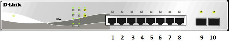
The D-Link DGS-1210-10 smart switch looks approximately like the drawing in the above figure. There are actuallt two variants of the front panel in this model, with a different arrangement of the RJ45 ports, but mine is like the above drawing. The ports are numbered, from left to right, in the order 1 .. 10. VLAN configuration in theory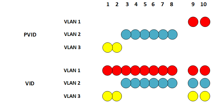
Two parameters are used on these switches to configure asymmetric VLANs. The PVID (Port VLAN ID) parameter tells to which VLAN each port belongs. As shown in the above figure, PVID specifies that VLAN 1 contains ports 9-10, VLAN 2 contains ports 3-8, and VLAN 3 contains ports 1-2. It is not possible to leave some ports unassigned to any VLAN. By default, at the beginning all ports are part of VLAN 1, called default, which cannot be deleted. It is likewise impossible for a port to belong in two or more VLANs. The VID (VLAN ID) parameter is set for each port on each VLAN. It tells to which VLAN traffic is routed from this port. In the above figure, for example, the VID of VLAN 3 tells that traffic from port 1 (which belongs to VLAN 3 as defined by its PVID) in VLAN 3 (yellow) is routed to ports 2, 9 and 10. The VID of VLAN 1, on the other hand, tells that traffic from ports 9 and 10 (as specified by the PVID of this VLAN) is routed to all other ports. There is no possibility, however, for traffic to be routed from ports 1-2 on VLAN 3 to ports 3-8 on VLAN 2, and vice versa. Ports 9-10 on VLAN1 have unrestricted access to all ports on VLANs 2 and 3. A given VID controls traffic between two ports in different VLANs in only one direction, so to have a working bi-directional traffic between these two ports you need a properly configured VID on each of these ports. A conceivable use for VIDs that only allow unidirectional traffic to a switch port is to completely stealth all L3 protocols on a host connected to this port. This host, with appropriate software, can then log all L3 access attempts by other hosts, while the hosts attempting a contact/connection only see their L3 packets disappear into a black hole without ever getting a reply. This is different from getting a message saying that a given L3 protocol and/or port is closed. A closed protocol/port proves that there is a host at the given address, which may be worth targeting with a deeper scan. In this particular example, no additional smart switches are used to extend the VLANs. All VLANs start where frames enter a port, and end where frames leave a port. You can of course extend one particular VLAN by connecting an unmanaged switch to one of the untagged VLAN's ports on the DGS-1210. All ports on the unmanaged switch belong then de facto to this VLAN. Switch configurationTo avoid losing contact with the switch during its configuration, connect the computer used to manage the switch to port 9 or 10 (i.e., the ports that will remain on VLAN 1). 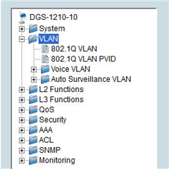
The VID and PVID parameters are configured in the 802.1Q VLAN and 802.1Q VLAN PVID dialogs, respectively. 
As mentioned above, asymmetric VLANs are needed in this case. Do yourself a favor now by navigating to VLAN, 802.1Q VLAN in the menu, ticking the Enabled radio button of the Asymmetric VLAN setting, then clicking the Apply button. If you do this after you have created and configured the VLANs, you will lose all their configuration and will have to redo everything once more. The title bar of the dialog changes accordingly to 802.1Q Asymmetric VLAN Settings (but the 802.1Q VLAN item in the menu does not change name). 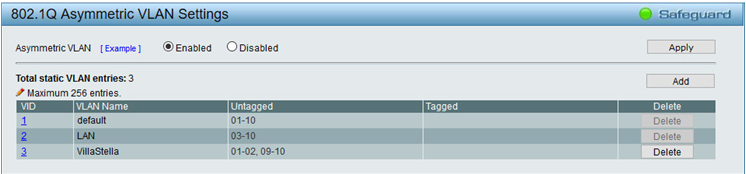
The default VLAN (which is VLAN 1) is pre-defined in the 802.1Q Asymmetric VLAN Settings dialog. Make sure that all its ports are untagged . The only reason to use a tagged port is when you want to extend multiple VLANs onto another smart switch by using only one port on each switch. VLAN traffic is tagged internally within the switch, so that the switch knows which frames belong to which VLAN. When an untagged frame enters an untagged port from the LAN, the switch inserts an IEEE 802.1q 4-byte field between the Source MAC field and the EtherType field, and when a tagged frame is about to exit an untagged port, the switch strips off this field. When a frame enters a tagged port of the switch from the LAN, instead, the switch expects the frame to be tagged, and looks for the IEEE 802.1Q header in the frame. When a tagged frame is about to leave a tagged port, the IEEE 802.1Q header is left in the frame. As a result, the device connected to a tagged port must be able to both create and process IEEE 802.1Q tagged frames. In D-Link DGS-1210 switches, a port that is meant to send and receive tagged frames must be configured as tagged in the 802.1Q Asymmetric VLAN Settings dialog.
IEEE 802.1Q states that an untagged frame that enters a tagged port is tagged by the switch as belonging
to the
default VLAN
(VID = 1). I have
not tested whether this is true on the DGS-1210-10. D-Link 1510 series switches support "mixed
VLANs", which in my understanding means that traffic can consist of a mix of tagged and untagged
frames. The DGS-1210 series lacks this setting. Note that only the VLAN number is used in the dialog (in this case, 1). If you need to reconfigure VLAN 1, click the number 1 leftmost in the table. In the same dialog, use the Add button to add two more VLANs. In this example, they are named LAN (for the home network) and VillaStella (for the cottage). Configure them as shown in the above figure. 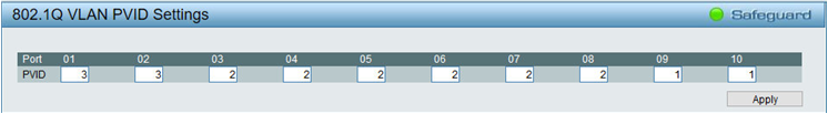
Navigate to the 802.1Q VLAN PVID dialog and configure the PVID settings for all ports, as shown above. Also in this case, note that only the VLAN number is used (1, 2, or 3). Click Apply. Note also that, at some point during the configuration, you may lose contact with the switch if the computer used for managing the switch is located on VLAN 2 or 3, instead of 1 as suggested above. 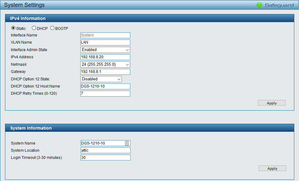
Next, navigate to System, System Settings, IPv4 Information and type the name of the VLAN you will use to manage the switch in the VLAN Name text box. Click Apply in the dialog. This VLAN becomes impossible to delete or rename, until you specify a different VLAN in VLAN Name. The natural choice in this case is to use LAN (i.e. VLAN 2), so that no hacker with a computer on VLAN 3 can manage the switch, even if she knows the switch login password and is able to spoof the MAC and IP addresses of the management computer. If your computer is still connected to VLAN 1, at this point you need to connect it physically to a VLAN 2 port to regain access to the switch. The configuration takes effect piecewise as you press the Apply button in each dialog. If you lose contact with the switch, try first to physically connect the computer to a port on another VLAN. If you make a configuration mistake, or there is a conflict with some security settings in the switch configuration, or the switch becomes stuck in an endless loop and unresponsive, you may permanently lose contact with the switch. If all else fails, you may need to reset it to factory defaults to regain control. In this case, it is good to remember that the default IPv4 address of the switch is 10.90.90.90, and that the management computer must have at least one Ethernet interface configured on the 10.x.x.x network (it is perfectly fine, for example, to use a computer with two Ethernet cards, one on the 192.168.x.x network and the other on the 10.x.x.x network, both connected to the same switch). Once finished configuring and testing the VLANs, you must save the configuration, lest it will be lost the next time the switch reboots. To save the configuration, click Save, Save configuration in the toolbar, select a configuration bank (usually config_id 1), and click Save Config. It is a good idea to backup the switch configuration to the management computer every time you are finished with a configuration task and are sure that the new configuration works. Keep several successive backups, just in case you need to revert to an earlier version of the configuration. As a final step in configuring the VLANs, connect the computer you will continue to use for managing the switch to a port of the appropriate VLAN. Incidentally, the DGS-1210, once properly configured, does not reply to ICMP probes or connection attempts from other VLANs and IP addresses than the ones configured for management. TestA simple way to test the VLANs is to ping the whole IP address range of the network from a computer connected to VLAN 1 (e.g. with Angry IP Scanner). This computer should be able to ping all devices on the network. Now connect the computer to VLAN 2 and repeat the scan. It should only detect the devices on VLANs 1 and 2. Repeat with the computer connected to VLAN 3. Now it should only detect the devices on VLANs 1 and 3. Additional stepsAs additional steps, my network needed WiFi and DHCP server to be disabled on the router (to avoid the problem mentioned above), activating the DHCP server on the CPE210 access point of the guest WiFi, and adding a second CPE210 as DHCP server and WiFi access point for VLAN 2. Concluding remarksThe CPE210 only provides 2.4 GHz WiFi. In my case, I decided to use the 2.4 GHz band because it passes through walls and obstacles with less attenuation than the 5 GHz band, and therefore has a wider range in real-world situations. If 5 GHz WiFi is preferred, e.g. for its lesser likelihood of interference from other equipment, a CPE510 can be used. These devices are cheap enough that it is reasonable to use multiple ones in a home network, and so far have proven to be more reliable than many WiFi devices designed for home use. For example, many CPE models have additional functions not typically found in home equipment, like periodically pinging their server (usually the router) and automatically rebooting if they discover that their connection to the server has been lost. This minimizes the need for manual intervention by an administrator if a temporary malfunction breaks a connection. TP-Link also markets reasonably priced WiFi devices with sharply directional capabilities like the CPE710, which has a built-in high-gain parabolic antenna, weatherproofing, a greater geographic range and built-in lightning/overvoltage protection. D-Link markets a number of models in the DGS-1210 series of smart switches, including units with PoE capabilities and up to 52 ports. For home networks, however, fanless models are most desirable for their silent operation, and this limits the choice of suitable models to the low end of the range. In fact, in a relatively small home network, it may be a good idea to forego a single fan-cooled smart switch with PoE capabilities and enough ports for the whole system, and instead combine a fanless smart switch with a separate, fanless non-managed PoE switch and, if necessary to add even more ports, a fanless unmanaged switch with 16 or 24 ports (or a semi-smart switch with symmetric VLANs only). This newer page continues where the present page leaves off, and discusses how to extend asymmetric VLANs onto a second switch, and to configure aggregated links between the two switches. |